Friday, October 28, 2016

Hey everyone, do you think you can find all the words in this word search? But more specifically on the different equipment associated with maritime. Leave a comment on how long it took you to find it and what you words you want to see next.
#DailyWordSearch #MuseumOfMNCNY


Radio Direction Finder:
A radio direction finder can determine the direction from which radio signals come with great precision. By taking two or more readings from radio beacons the navigator can, by using a chart showing the location of the beacons, determine the position of own vessel. Beacons are identified by a code, often a two or three letter Morse code. The codes are shown on the charts. The Radio Direction Finder can also indicate the direction to another vessel, whether the vessels are to meet, and more importantly if a vessel is in distress. A radio direction finder (RDF) is a device for finding the direction, or bearing, to a radio source. The act of measuring the direction is known as radio direction finding or sometimes simply direction finding. Using two or more measurements from different locations, the location of an unknown transmitter can be determined; alternately, using two or more measurements of known transmitters, the location of a vehicle can be determined. Radio Direction Finder is widely used as a radio navigation system, especially with boats and aircraft. Radio Direction Finder systems can be used with any radio source, although the size of the receiver antennas are a function of the wavelength of the signal; very long wavelengths (low frequencies) require very large antennas, and are generally used only on ground-based systems. These wavelengths are nevertheless very useful for marine navigation as they can travel very long distances and "over the horizon", which is valuable for ships when the line-of-sight may be only a few tens of kilometers. For aerial use, where the horizon may extend to hundreds of kilometers, higher frequencies can be used, allowing the use of much smaller antennas. An automatic direction finder, often capable of being tuned to commercial AM radio transmitters, is a feature of almost all modern aircraft.

ITT Mackay Marine – 4004A

Manufactured by: ITT Mackay Marine
Model: 4004A
Radio Frequencies: 200-550KHz


Radio Corporation of America – AR-8714C

Manufactured by: Radio Corporation of America
Model: AR-8714C
Power Requirements: 115VAC
Radio Frequencies: 190-520KHz


C Plath Hamburg – GPE277

Manufactured by: C Plath Hamburg
Model: GPE277
Radio Frequencies: 240-540KHz, 2.12-2.24MHz
Power Requirements: 220/115VAC, 0.1/0.2 Amp or 24V/12VDC, 0.5/1.0 Amp


Saturday, October 22, 2016

Hey everyone, do you think you can find all the words in this word search? But more specifically on the different equipment associated with maritime. Leave a comment on how long it took you to find it and what you words you want to see next.
#DailyWordSearch #MuseumOfMNCNY


ARPA: Automatic Radar Plotting Aid
Developed for marine usage in the 1970’s. Fittings aboard tankers were made mandatory in 1982, or other classes of ships soon after. On an ARPA the radar observer can designate a “target” ship of interest and the ARPA calculates the speed and course of the ship and assesses the risk of collision. Targets may also be “acquired” automatically and tracked. A number of targets can be tracked simultaneously. A “dangerous” target (one having a risk of collision) will be highlighted and an alarm will sound. On any target being tracked, the closest point of approach (CPA) and time to closest point of approach (TCPA) are calculated and displayed. Development of ARPA started after the accident when the Italian liner SS Andrea Doria collided in dense fog and sank off the east coast of the United States. ARPA radars started to emerge in the 1960s and, with the development of microelectronics. The first commercially available ARPA was delivered to the cargo liner MV Taimyr in 1969 and was manufactured by Norcontrol, now a part of Kongsberg Maritime. ARPA-enabled radars are now available even for small yachts.

Raytheon Marine Co. – RAYCAS V 1660/12SS

Manufactured by: Raytheon Marine Co.
Model: RAYCAS V 1660/12SS
Date of Mfg: 5/82 (Display), 2/82 (Transceiver)
Power Requirements: 115VAC
Operating Frequency: 3070 +-50 MHz, Output power 60KW

Pulse Repetition Frequencies: 3600, 1800, 900 Hz

Friday, October 21, 2016

Hey everyone, do you think you can find all the words in this word search? But more specifically on the ten different types of industries associated with maritime. Leave a comment on how long it took you to find it and what you words you want to see next.
#DailyWordSearch #MuseumOfMNCNY


RADAR: Radio Detection and Ranging
Developed just before WWII, Radar operates by generating a microwave radio frequency pulse and directing it in a narrow beam from a rotating antenna. After the pulse is transmitted the receiver detects the echoes and amplifies them to produce bright spots or areas on the indicator. The time between the transmitted pulse and echoes is interpreted as distance (range) from own ship.  As used aboard ships and other surface craft, radar data are displayed on a plan position indicator, a map like display with own ship in the center. Other vessels, buoys, land masses show up as bright spots or areas on a dark background.  Using a reflection plotter and plotter pencil (similar to a grease pencil), the radar observer can, by successive plots of other vessels, track and calculate the movements of other vessels and assess any risk of collision. Radar is an object-detection system that uses radio waves to determine the range, angle, or velocity of objects. It can be used to detect aircraft, ships, spacecraft, guided missiles, motor vehicles, weather formations, and terrain. The modern uses of radar are highly diverse, including air and terrestrial traffic control, radar astronomy, air-defense systems, antimissile systems, marine radars to locate landmarks and other ships, aircraft anti-collision systems, ocean surveillance systems, outer space surveillance and rendezvous systems, meteorological precipitation monitoring, altimetry and flight control systems, guided missile target locating systems, ground-penetrating radar for geological observations, and range-controlled radar for public health surveillance.


Raytheon Marine Co. – RAYCAS V 1660/12SS

Manufactured by: Raytheon Marine Co.
Model: RAYCAS V 1660/12SS 
Date of Mfg: 5/82 (Display), 2/82 (Transceiver)
Power Requirements: 115VAC
Operating Frequency: 3070 +-50 MHz, Output power 60KW

Pulse Repetition Frequencies: 3600, 1800, 900 Hz

Friday, October 14, 2016

Hey everyone, do you think you can find all the words in this word search? But more specifically on the different types of boats there are. Leave a comment on how long it took you to find it and what you words you want to see next.
#DailyWordSearch #MuseumOfMNCNY


Motor-Generator:
On ships built before the 1950's (and some after), the electrical power was direct current (DC), often 220 Volts, but some ships had 110 Volts DC.  This power was suitable for running compressor and winch motors and lights.  However few, if any, electronic equipment’s could use the ships voltage directly.  Hence the need for motor-generators (sometimes called rotary converters).  Often a motor-generator was included in a "package" of electronic equipment, such as radar, gyrocompass or loran.
In the 1950's ships were built with alternating current (AC) electrical systems. Most often this power was generated at 440 Volts, 60 cycles per second, three phase. This power is suitable for running large motors, as for winches and compressors; for lights and many electronic equipment the voltage is stepped down by a transformer to 115 or 230 Volts, single phase.  Ships built in Europe and South America tended to generate 380 Volts, 50 cycles per second, three phase. 
Many electronic equipment’s can operate with alternating current, 115 or 230 volts 50 or 60 cycles per second.  However, some equipment, particularly radars and gyrocompasses, required 1000 or 800 cycles per second.  Motor-generators fulfilled this requirement, being driven from the three phase alternating current or from direct current. Beginning in the late 1960's, certainly in the 1970's, electronic equipment used solid state converters, which could accept ships DC or AC power and provide voltage(s) required by the equipment, whether DC or AC.
Just below is images of a Motor-Generator:
Transmotor Copenhagen Denmark – ACMA-25

Manufactured by: Transmotor Copenhagen Denmark
Model: ACMA-25
Input Power: 440 VAC 3 phase 60 Hz, 0.8 A
Output Power: 115 VAC 1 KHz 1 Phase 250VA


Denki SYOKOSYA Co – MG-618-1
Manufactured by: Denki SYOKOSYA Co, Ltd, Tokyo Japan
Model: MG-618-1
Date of Manufacture: April 1974
Input Power: 220 VAC 3 Phase 50-60 Hz, 3.15 A
Output Power: 100 VAC 6A 1 Phase 800/1000Hz   100 VAC 1.5 A 1 Phase 50/60Hz


Monday, October 10, 2016

Marine Weather Facsimile:
Facsimile (fax) is a means of providing weather information to ships at sea.  The information is presented as a chart (map), showing barometric high pressures, low pressures, pressure gradients, wind speed and direction, and temperature. Schedules for facsimile weather broadcast were provided in marine publications and could also be sent via facsimile.
Early Facsimile recorders (into the 1970's) required a navigator to listen for a signal, select the correct speed, start the recorder and manually synchronize the recorder with the signal.  In the 1970's fax recorders became automatic, starting at a start signal, synchronizing before the text of the broadcast, then stopping when the end of the broadcast is received.

Below is some examples of marine weather facsimile:

Alden - Marine Fax IV

Manufactured by: Alden
Model: Fax IV
Power Requirements: 12VDC 4 Amp
Operating Frequencies: Synthesized 2-25KHz


Furuno Electric Co. LTD - FAX - 143II

Manufactured by: Furuno Electric Co. Ltd
Model: FAX - 143II
Date of Manufacture: 1982-4
Power Requirements; 115/230 VAC
Operating Frequencies: 3-23KHz 

Friday, October 7, 2016

Hey everyone, do you think you can find all the words in this word search? But more specifically on the different types of things associated with maritime. Leave a comment on how long it took you to find it and what you words you want to see next.
#DailyWordSearch #MuseumOfMNCNY
Loudhailer Horn
The loudhailer can provide voice communications with on-deck crew members, shore personnel if the vessel is docked or close to shore, and to close by vessels. When the loudhailer is not transmitting voice it is a sensitive listener for anyone who answers the hail. Many loudhailers include a horn function which can be operated by pressing the push-to-talk button. Some loudhailer-horns include a timer so that the appropriate fog horn signals are sounded at the correct intervals, especially useful when a vessel is anchored. Loudhailer-horns are more commonly used on smaller vessels; such as yachts, fishing vessels, and tug boats.

Raytheon Marine Co – Ray350A

Manufactured by: Raytheon Marine Co.
Model: Ray350A


Ray Jefferson / Jetronic Industries, Inc – 314

Manufactured by: Ray Jefferson / Jetronic Industries, Inc
Model: 314


Wednesday, October 5, 2016

Hey everyone, do you think you can find all the words in this word search? But more specifically on the different types of fish caught by maritime workers. Leave a comment on how long it took you to find it and what you words you want to see next.
#DailyWordSearch #MuseumOfMNCNY

Loran C
The Loran C system came into side-spread use during the 1970's.  A Loran C chain, called GRI (Group Repetition Interval) consists of a master station and two to five slave stations.  The area covered is much larger that a Loran A station pair.  At first an operator had to determine the time differences and plot them on a chart, as discussed above.  But soon the time differences were calculated automatically and displayed continuously and could be plotted on a chart.  Soon after, the time differences were converted directly into degrees and minutes of Latitude and Longitude.  The absolute accuracy of Loran-C varies from 0.1 to 0.25 nautical miles. Repeatable accuracy is much greater, typically from 60 to 300 feet.
Coverage is continuous within the area of coverage but the Loran system is not used worldwide.  
The Loran C system is also used by aircraft.

SI-TEX/KODEN – 787C
Manufactured by: SI-TEX/KODEN
Model: 787C
Serial Number: 2487


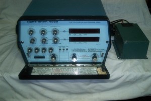
Digital Marine Electronics Corp. – Northstar 6000

Manufactured by: Digital Marine Electronics Corp.
Model: Northstar 6000
Operating Frequency: 100KHz
Power Requirement: 10-40 VDC 2 Amps


Loran C Navigator
A LORAN C Navigator is essentially a computer with pre-loaded data, contained in an enclosure along with the receiver.
The recieved data consists of time differences between two (or more) station pairs.  One station of the pair is always the master station, the other is a slave station.  Each LORAN C chain consists of a master station and two to five slave stations.  The operator selects the optimal two pairs to obtain the data.
By matching successive fixes of the received data with the pre-loaded data, a navigator can show latitude-longitude, own ships speed and course, course to steer to a chosen way point, time to get to the way point.  Some other functions may be available.
Furuno – LC-80

Manufactured by: Furuno
Model: LC-80
Date of Mfr: 1985-1


Trimble Navigation – 200

Manufactured by: Trimble Navigation
Model: 200
Operating Frequency: 100KHz


Simrad – CC

Manufactured by: Simrad (International Navigation Corporation)
Model: CC
Date of Mfg: 8-77
Power Requirements: 115VAC


Micrologic – ML-320

Manufactured by: Micrologic
Model: ML-320
Power Requirements: 8-18VDC 3 Amps
Operating Frequency: 100KHz


Navidyne Corp. – ESZ-7000

Manufactured by: Navidyne Corp.
Model: ESZ-7000

Operating Frequency: 100KHz

Monday, October 3, 2016

LORAN:
Long Range Navigation
Early Equipment’s required the operator to work dials until two waves were superimposed on the scope tube.  The time difference between master and slave pulses then was read from the dials.  Two (or more) station pairs had to be read to determine the ships position.  A chart with loran lines of position overprinted was used in conjunction with the loran.  Own position was at the intersection of two lines. LORAN suffers from electronic effects of weather and the ionospheric effects of sunrise and sunset. The most accurate signal is the ground wave that follows the Earth's surface, ideally over seawater. At night the indirect sky wave, bent back to the surface by the ionosphere, is a problem as multiple signals may arrive via different paths. The ionosphere's reaction to sunrise and sunset accounts for the particular disturbance during those periods. Magnetic storms have serious effects as with any radio based system. Loran uses ground based transmitters that only cover certain regions. Coverage is quite good in North America, Europe, and the Pacific Rim.

Loran A
LORAN-A was a less accurate system operating in the upper medium wave frequency band prior to deployment of the more accurate LORAN-C system. For LORAN-A the transmission frequencies 1750 kHz, 1850 kHz, 1900 kHz and 1950 kHz were used. LORAN-A continued in operation partly due to the economy of the receivers and widespread use in civilian recreational and commercial navigation. LORAN-A was used in the Vietnam War for navigation by large United States aircraft (C-124, C-130, C-97, C-123, HU-16, etc). A common airborne receiver of that era was the R-65/APN-9 which combined the receiver and cathode ray tube (CRT) indicator into a single relatively lightweight unit replacing the two larger, separate receiver and indicator units which comprised the predecessor APN-4 system. The APN-9 and APN-4 systems found wide post-World War II use on fishing vessels in the U.S. They were cheap, accurate and plentiful. The main drawback for use on boats was their need for aircraft power, 115 VAC at 400 Hz. This was solved initially by the use of rotary inverters, typically 28 VDC input and 115 VAC output at 400 Hz. The inverters were big and loud and were power hogs. In the 1960s, several firms such as Topaz and Linear Systems marketed solid state inverters specifically designed for these surplus LORAN-A sets. The availability of solid state inverters that used 12 VDC input opened up the surplus LORAN-A sets for use on much smaller vessels which typically did not have the 24-28 VDC systems found on larger vessels. The solid state inverters were very power efficient and widely replaced the more trouble prone rotary inverters.
LORAN-A saved many lives by allowing offshore boats in distress to give accurate position reports. It also guided many boats whose owners could not afford radar safely into fog bound harbors or around treacherous offshore reefs. The low price of surplus LORAN-A receivers (often under $150) meant that owners of many small fishing vessels could afford this equipment, thus greatly enhancing safety. Surplus LORAN-A equipment, which was common on commercial fishing boats, was rarely seen on yachts. The unrefined cosmetic appearance of the surplus equipment was probably a deciding factor. The Loran A system was terminated December 31, 1981. 
An illustration of a Loran A is down below:

DX Navigator

Model: DX Navigator
Power Requirement: 115VAC
Frequencies: 1850 KHz (1), 1950 KHz (2), 1900 KHz (3), 1750 KHz (4)
Basic Repetition Rates: 20Hz (S), 25Hz (L), 33 1/3 Hz (H)